Reduce Cooling Water Temperature with High-Performing, Sustainable Heat Exchangers
Processors are replacing shell and tube heat exchangers with plate and frame units, increasing efficiency.
By Sebastian Schill and Peter Leicht, API Heat Transfer
A top priority of companies today is to protect the climate while meeting energy demands. Many are looking to improve their thermal processes in an ecologically friendly manner. Oftentimes, this means replacing existing products with more energy efficient, sustainable choices. As this relates to heat exchangers, there are many variations, so it is important to understand the differences and relative performance of each.
Efficiency is a key sustainability driver, and it makes sense that the surface area of the plates or tubes in a heat exchanger directly correlates to a unit’s heat transfer potential. Efficient heat exchangers are designed to maximize the surface area between the two fluids while minimizing resistance to fluid flow through the exchanger.
For cooling purposes, the hot fluid output temperature is critical. Selecting the heat exchanger type and size for your process depends on a number of factors, including flow arrangement and design type.
Flow arrangement refers to the movement direction of the fluids within the heat exchanger in relation to each other. There are three main types: co-current or parallel, countercurrent and crossflow.
In a co-current arrangement, two fluids enter the exchanger at the same end and travel in parallel to the opposite side. This immediately puts the coldest material in contact with the hottest gas, resulting in a rapid initial temperature change. The inlet temperatures of the two fluids may be significantly different, but by the end of the process, they are relatively the same temperature.
The heat exchange rate in a co-current arrangement is lower than other flow patterns, so this arrangement requires a greater heat transfer surface area. This is because the incoming cooling medium, traveling in parallel with the hot fluid, is gradually warmed along the length of the heat exchanger. With cold water entering adjacent to the hottest area of the unit, the heat exchanger cannot cool below the outlet temperature of the cooling medium itself.
A major disadvantage of this arrangement is that the dramatic temperature difference at the inlet can lead to thermal stress, which can cause vibrations that can prematurely damage the unit.
A countercurrent arrangement is the complete inverse of the co-current design. Instead of the fluids entering at the same end, they enter at opposite ends and flow in opposing directions. In this arrangement, the temperature variance is at its maximum at the inlets and decreases to a minimum at the outlets.
In countercurrent configurations, the mean temperature difference between the cooling medium and the fluid being cooled is much more uniform along the length of the heat exchanger, significantly reducing thermal stress to the unit. Also, because the temperature difference is more consistent, there is less chance of fouling. The high turbulence promotes cleanliness within the unit. The high turbulence also produces high heat transfer coefficients, so a smaller surface area is required.
Lastly, a crossflow arrangement is when the two fluids flow perpendicular to one another. This is typically utilized when one fluid is a liquid and the other is a gas.
The most common type of heat exchanger is the shell and tube design. It is composed of a large number of small tubes arranged inside a cylindrical shell. In a shell-and-tube design, one fluid travels through the tubes while the other passes on the outside of the tubes and is confined by the shell.
There are many variations to a shell and tube design. The tubes can be arranged using a tube stack or tube bundle that can be either floating or fixed. The round geometry of the shell and tube design is well suited for a pressure vessel, which makes it a good choice for high pressure applications. It also is suited for high temperature applications due to its robust construction. Special materials such as graphite can be used, and fewer gaskets are required compared to a gasketed plate heat exchanger.
This type of heat exchanger also is suited for applications with large, differential volumetric flows between the hot and cold sides.

Generally, the flow pattern in a shell and tube heat exchanger is a combination of crossflow, co-current and countercurrent arrangements.
Although the shell and tube design has many advantages — and is the most popular heat exchanger in the industry — it is typically not the most efficient or environmentally friendly.
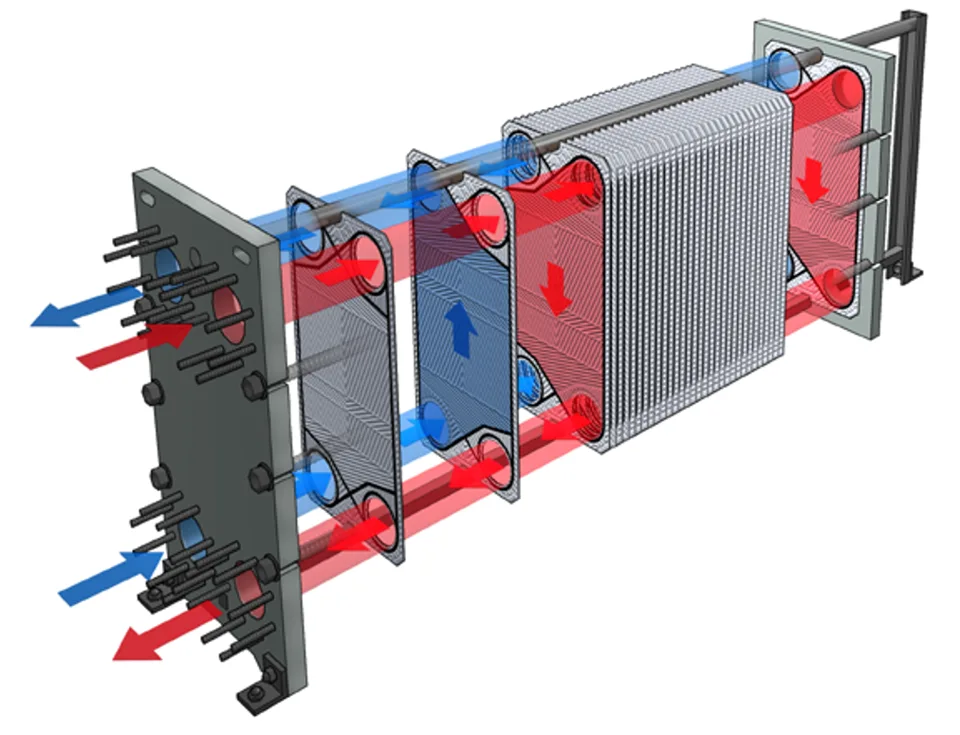
Another design is the plate heat exchanger, which has a countercurrent flow arrangement. In this design, a series of plates, instead of pipes, provides a set of channels for the fluids. As the fluids pass through the channels, they travel over the plate, or heat transfer surface. Because the plates occupy a small space but create a large surface area, plate heat exchangers take up significantly less floor space compared to a shell and tube design.
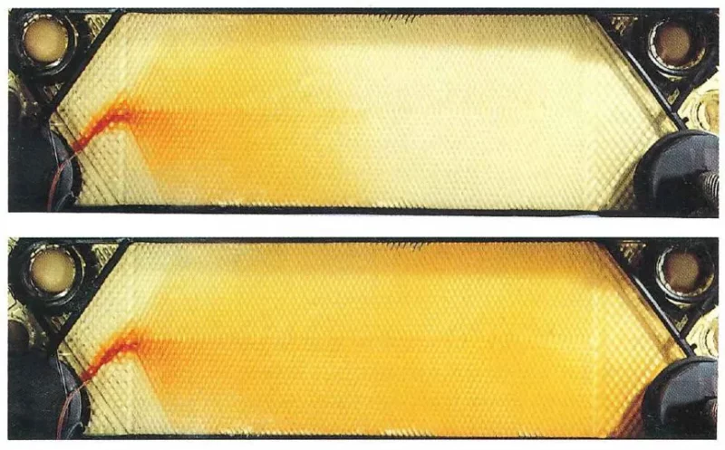
Less surface area is needed for plate heat exchangers, which means there is more surface area per installed volume. The distribution area ensures the flow of fluid to the entire heat transfer surface. This helps to prevent a stagnant area that can cause an accumulation of unwanted material on solid surfaces.
Plate heat exchangers are being used in place of shell and tube designs in some applications due to their compactness, ease of maintenance and efficiency. A plate heat exchanger is usually gasketed or welded, depending on its use and fluid flow. Advances in gasket and welding technology have made the plate-type heat exchanger increasingly practical. Welded plate heat exchangers can be used in high temperature and high pressure applications. They show their biggest benefit in liquid applications but also can be used for gas and gas-liquid mixtures.
In addition, crossing temperatures and low temperature approaches are possible with higher heat transfer coefficients and a countercurrent flow arrangement.
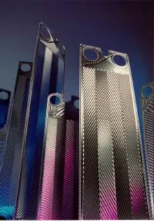
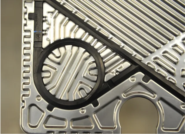
Plate-and-frame designs are available in different sizes and depths and constructed of a range of materials including stainless steel, nickel alloys and titanium alloys. The exchanger’s performance can be improved by the addition of fins or corrugations in one or both directions. This can expand the surface area and channel fluid flow, or induce turbulence. Some specialty corrugated plate patterns can ensure a high degree of turbulence over the whole plate. They also can help reduce fouling and ease cleaning.
Modern gasket designs in plate heat exchangers include glue-free and bolted construction. These features can help ease service, assembly and cleaning. With bolted gaskets, the heat transfer surfaces are accessible for inspection or mechanical cleaning by removing the bolts and rolling back the pressure plate. Another benefit of bolted gaskets is that they can be redesigned by adding or subtracting plates. This allows users to adjust capacity to meet changing needs while retaining the existing frame. This is an advantage compared to shell and tube units, where capacity is fixed at the level determined at the time of installation.
The compact design of plate heat exchangers means that transportation, erection and installation costs typically are all lower than shell and tube units. High quality plate and frame heat exchangers can operate efficiently for more than 10 years with little maintenance.
In conclusion, in this era of heightened environmental awareness and sustainability initiatives, energy-efficient products can help you achieve your company’s goals. Replacing shell and tube heat exchangers with plate and frame units can provide increased energy efficiency and cost savings over time. The counterflow arrangement of plate and frame heat exchangers is more efficient than shell and tube ones. Depending on the flow rate and temperature, heat transfer performance can improve due to the lower approach temperature differences and high temperature changes of a plate and frame heat exchanger. In addition to increased energy efficiency, a plate and frame heat exchanger uses less pump energy and less cooling water.